I bought a Mopi with hopes to use it to connect my Raspberry Pi 2 to my car battery. I came across this https://pi.gate.ac.uk/images/mopi/in-car.png which seems fairly straightforward but I don’t understand the S1 or S2 marking in the diagram for the MoPi. It doesn’t have the RP1 or RP2 markings on it either, but from what I understand those are the little pad thingys (sorry for technical terms) next to the power button.
Looking at the in-car schematic and the MoPi description on pi.gate.ac.uk here is my take on how this works.
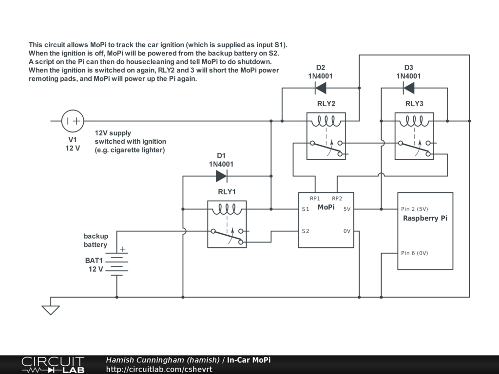
S1 and S2 are Source 1 and Source 2 (the screw terminals).
RP1 And RP2 the two jumper pins on the MoPi board (the little pad thingys).
Assuming the Pi is powered down (after an orderly shutdown on the backup battery), when the 12V comes on Relays 1 and 2 go to the upper position: Backup battery is disconnected and MoPi is connected to the 12V.
SInce there is no 5V yet, Relay 3 is still in the lower position. This effectively shorts the 2 jumper pins, giving the greatest chance the MoPi starts producing 5V. See the FAQ entry : “I connected a power source but MoPi won’t start…?”.
As soon as the 5V is there Relay 3 goes to the upper position, effectively removing the jumper.
Hope this helps.