I need to be able to use the Automation pHat and the Speaker pHAT on the same project/Raspberry Zero W. This is currently a problem due to the pin conflict on GPIO pin 40.
I already understand how to change the programming to address different GPIO ports so that’s the easy part.
What I would like is if you could give guidance as to the best place to cut input 3 from pin 40 and jumper it to another GPIO pin. Although I could figure it out you have the PCB layout and should be able to select the best point to make the cut and the best place to solder the jumper to. This would be much easier with a schematic and the eagle file like Adafruit and other have for their boards.
Might I suggest that on future boards you add a three pad jumper block so it would be easier for someone to make this change cleanly.
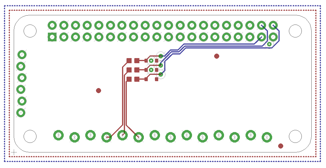
You may want to verify this with a multimeter but pin 40 - BCM21 - runs to the bottom most resistor/diode pair on the front of the board. I would probably cut just after the via that brings this trace from the back to the front of the board, and then jump copper enamel wire from between the resistor/diode (nice big pads to solder to) to the nearest available GPIO on the front side of the board.
If you wanted to conceal your bodge, you could cut just before this via on the back, then gently scrape away the resist over the via and use that to solder onto. I’d just do it on the front, since it’d be so much easier.
If I hadn’t already put a header onto the pHAT, I’d rip out the GPIO pin corresponding to pin 40 so I didn’t have to do any trace cutting at all, and there would be no extraneous trace connected to the pin (which could cause various analog-level signal issues, although I doubt they would cause a problem).