I would like to share the additions I have made to my Picade with a 12" screen. Thanks must go to @Dyltone for the button and voltage conversion ideas, and to @jopamo for the 12" screen and driver board suggestions, all from this thread: 12.1 Inch Display Question
My modifications involve two power buttons, the new Picade HAT, and a single 12V power source. All links to where I bought the items are below as well.
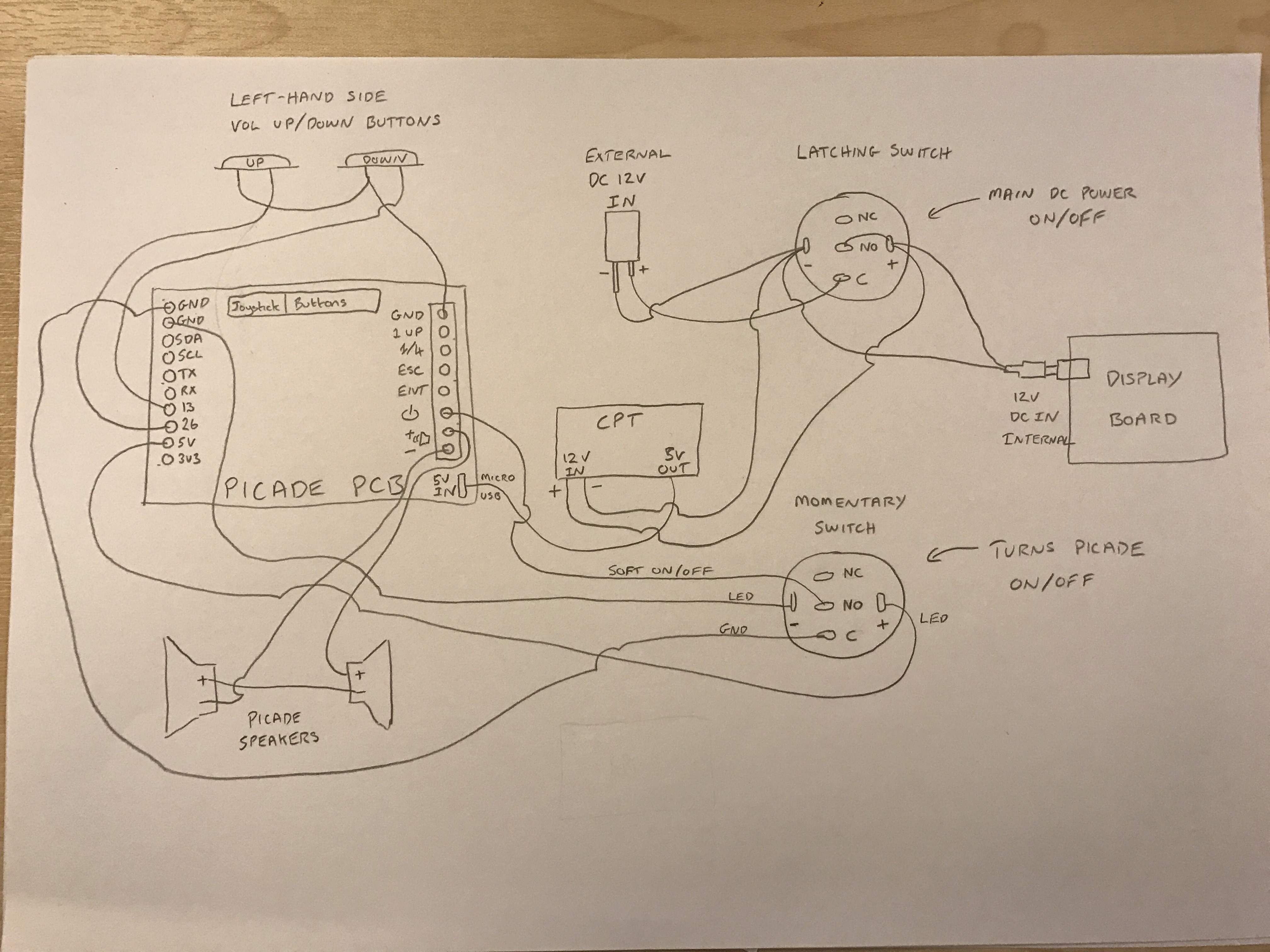
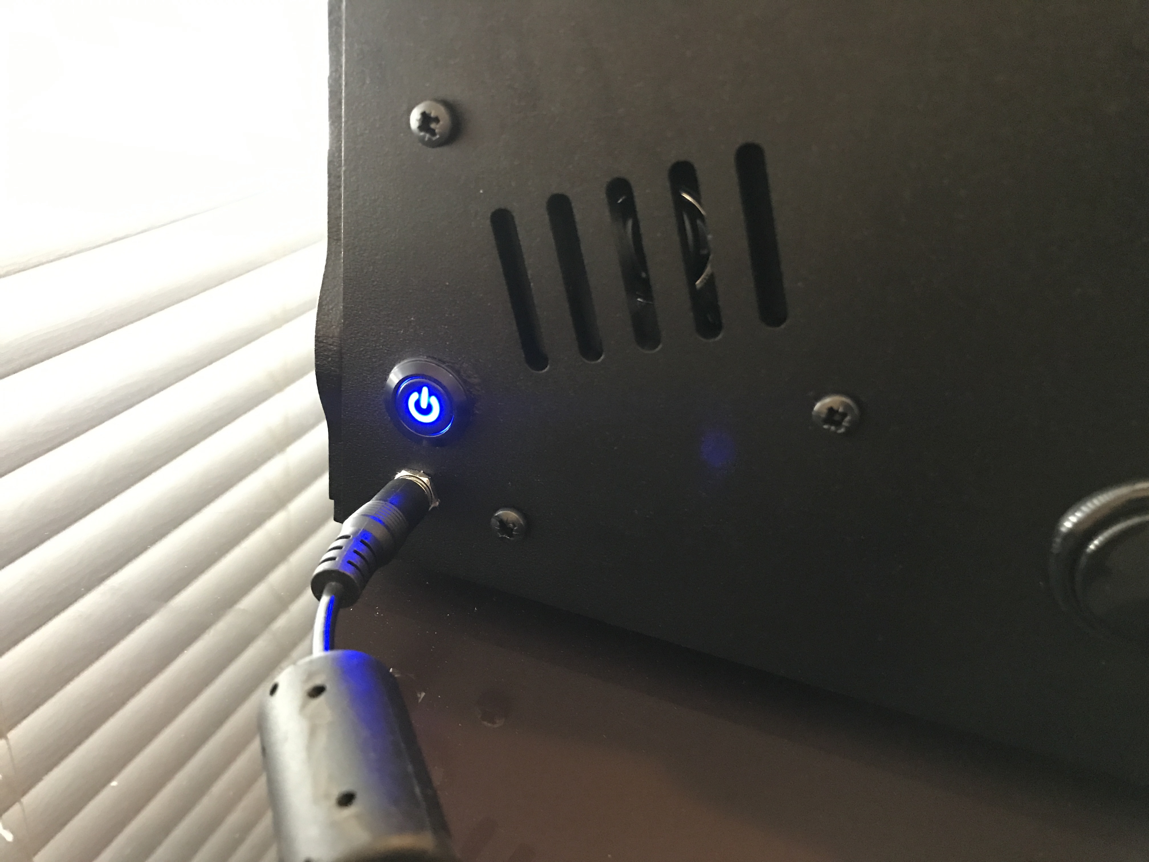
The key features this setup offers is the ability to have a single power source with a master on/off button, and an additional button that utilises Picade HAT’s Pi on/off feature. Both buttons light up when on for a nice visual feedback. Also, my setup allows you to have physical volume up/down buttons (missing from the HAT), and the wiring of both speakers together. A full circuit diagram is below too.
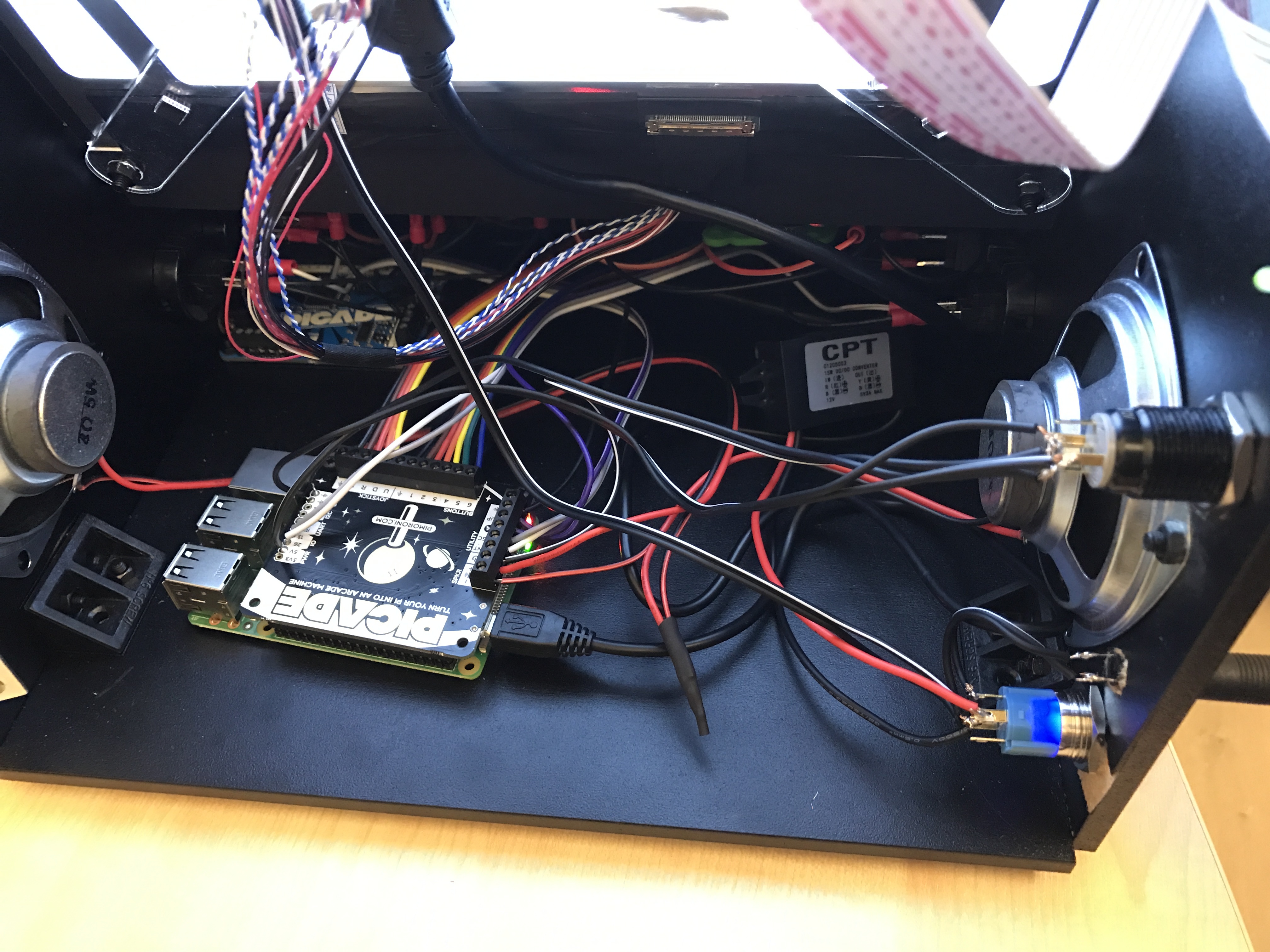
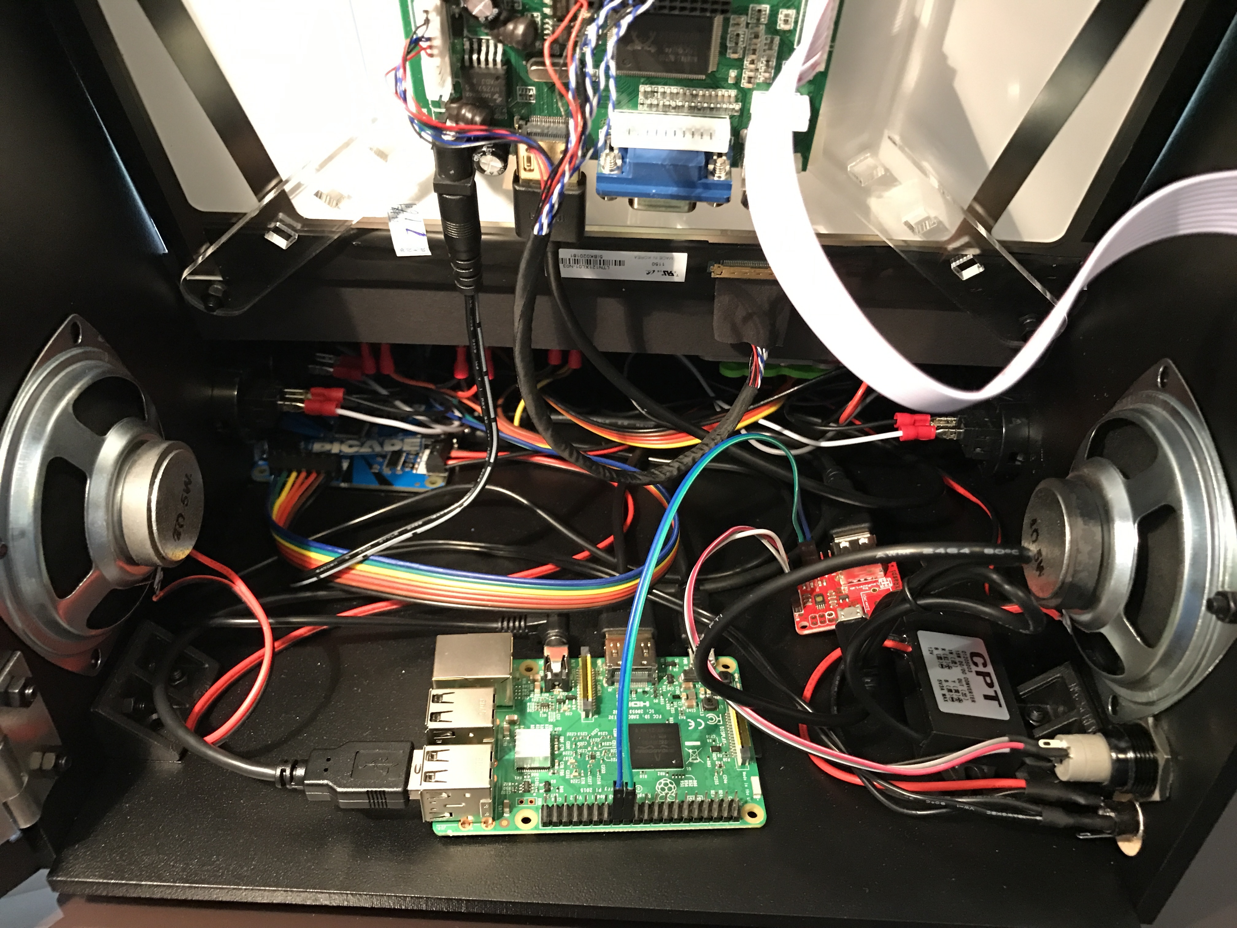
Here are some pictures (yes, not the neatest of mods):
1.5M DC Power Cable/Lead -5.5mm x 2.5mm- Male Plug to Bare Ends (you won’t need 1.5m, but the extra wire was used to solder everything together) - http://www.ebay.co.uk/itm/371610088443
5 x 2.5mm x 5.5mm Round Panel Chasis Mount Female Socket DC Connector (to be honest, these aren’t long enough for the fastening nut to hold it in place, so had to superglue it in) - https://www.amazon.co.uk/gp/product/B00WZ8210C
Unfortunately, I can’t take credit for designing my build… I copied @Paulcheffus post and then asked him a 1000 questions. He’s the real electrical genius and I want everyone to know.
I can only take credit for the joystick/button/lighting upgrades as those were my ideas.
May I ask a question… are you happy with the design of two types of switches rather than using a 3rd party power solution (atxraspi, powerblock, etc) and having a single power button?
@Dyltone yes I know what you mean with the switches, but as I have the Picade HAT I had to use the two. This is because the HAT doesn’t automatically turn on unless you press the power button, so I’d have needed a 2nd switch anyway.
Just thinking out loud, and not sure this would work. I’m would think you could have used the LED leads from a single power button to complete the start up circuit on the HAT power button or something similar.
Either way, beautiful work and thanks for sharing. I love this little cade.
Personally I wouldn’t use that socket as the rating is not high enough. The socket I used for mine was this one
2.5mm version also available
Which one you require will depend on the size of the plug on the PSU you are using.
The rating of the switch can be quite low as it doesn’t actually switch the full load of the PSU as this is taken care of by the unit you use such as the ATX Raspi / Powerblock or Picade HAT.
That one says it works with panels upto 3.1mm thickness is that enough to screw it to the panel?
Edit: Have checked and the panels seem to be approx 5mm thickness.
I’ll keep looking, there must be some sockets available somewhere that have a rating of 12vDC 3A, and can do 5mm thickness, as the 1A ones exists, so based on that alone others must also surely.
@Dyltone It’s a good thought suggesting the LED leads, but I don’t think the light terminals are linked to the switch because I can light up the LED whether the switch is on or off.
@Paulcheffus I didn’t think to look at the rating of my power socket, so thanks for the tip! The version I used didn’t show a rating so may find an alternative just in case.
You could do what I did and recess the socket from the inside using the flat drill bit as shown. Just be careful that you don’t drill all the way through.
Thanks for that I did wonder why there was a white bit there, now I know!
I think I have 2 choices basically do what you have done.
or I noticed that the socket you use had the thread at the front, not behind, so I thought I could just make a slightly small hole in the panel and screw the thread into the hole, I shouldn’t then need the nut on the other side to hold it in I am hoping at least.
This is my setup so far. Single power source with ATXRaspi. I still need to secure the Pi and do some cable management but overall I am very happy with the results.
Thanks to Dyltone and Paulcheffus for answering all my silly questions and findon for the artwork.
Really impressed with this setup Luis. Actually have a few questions on this:
Would you be able to sketch out the connections? So I am sure that this is what I am seeing:
your 12v Power source is fed into the cab, branched out to direct 12v power to lcd driver board and 12v in to the 12vto5V CPT.
from 5V out from CVP goes to ATXRaspi and from there you power RaspPi via GPIO and not via micro usb.
Am I correct?
Post-Edit: After seeing ATXRaspi intro video I realized that you must still power PI from micro USB, GPIO are used to send commands do Pi to enable boot/reboot/shutdown. #newbie
The CPT that I got has a micro usb output that gets connected to the ATXRaspi 5v input and from there it gets connected to the Pie via USB A to Micro USB cable (i got this cable from the ATXRaspi website).
@Luis
already have the 12v -5V power converter AND the ATX Raspi :)
now only waiting for the LCD Driver board to test assemble everything
and hope that Picade BYO Screen becomes available soon ^_^
I’ve actually bought an OnOffShim as the ATXRaspi isn’t readily available here in the UK, and all I need it for is turning on and safely shutting down. Maybe I’ll just get a momentary instead. In fact I’ve found the exact same switch but a momentary one, so that’s good.