Hi everyone, my project is to build a greenhouse environment monitor and watering controller.
This will be my second attempt to build such a device. The Mk. 1 never worked too well. If left to its own devices, the plants would end up too dry or the greenhouse flooded! I still don’t really know how I am going to avoid those two extremes with the Mk. 2, so read on, and if you have any suggestions, please let me know.
I will describe how the Mk. 1 worked in more detail in a later post, but to summarise, it consisted of a single home-made soil moisture sensor, a Picaxe 08M2 microcontroller and a 12V boat bilge pump. It was powered by a 12V SLA battery which was kept charged by a solar cell. It was one of my very earliest electronics hobby projects.
The Mk. 2 will add temp & humidity monitoring inside the greenhouse, and possibly multiple soil probes. It will allow remote adjustments of the desired settings (maybe only from within my LAN) and data logging to a MySQL database on a remote server. The logged data can be viewed through a web interface which I have already developed. You can see examples of how that looks on my weather station and indoor sensor links below.
The Mk 2 could go two different ways in terms of technology. I am going to try to progress with two designs and see which one starts to look like the ultimate winner.
Technology Choice #1: Wemos D1 Mini Pro. This is a dev board based on ESP8266 and I would be developing in C/C++ using the Arduino IDE. I am very familiar with this approach and have used it recently in my weather station and the indoor sensors in my home.
Technology choice #2: Pi Zero W, with an Automation pHAT. On a recent shopping trip to Sheffield, I visited Pimeroni HQ and met and talked with their friendly staff including Phil & Paul, who took an interest in my project and convinced me to consider this alternative approach.
Today, I installed the latest Raspbian Jesse Lite onto a 16GB micro-sd and booted up the Zero W for the first time. I then established the connection to my WiFi network and enabled SSH so I can remote log-in to the Pi. Don’t worry, I changed the password!
Then I installed wavemon and went walkabout with my laptop and the Pi Zero to see what signal strength I could get outside the house, and, in particular, in the greenhouse. The reasonably good news was that inside the greenhouse with the doors shut, I was just about getting enough signal to connect to the WiFi. Signal strength was around -80dBm and quality around 40%. However, once encased in a weatherproof project box and sandwiched between the Automation pHAT and another PCB with various components mounted, I am not at all confident that the signal will be good enough.
I judge that the built-in pcb antenna is a little better than that of the pcb antenna Wemos D1 Mini, and the ceramic antenna on the Wemos Mini Pro. But not as good as the antenna built into my laptop and not as good as the Wemos Mini Pro with an external 3dBi antenna connected. None of that is a surprise. I really would feel more confident about using the Zero if I could attach an external antenna.
Et Voila! An article about adding an external antenna. And… I’ve already got a spare antenna and a suitable connector to solder to the Zero. I happen to have these because I accidentally damaged the connector on a Wemos Mini Pro and had to replace it.
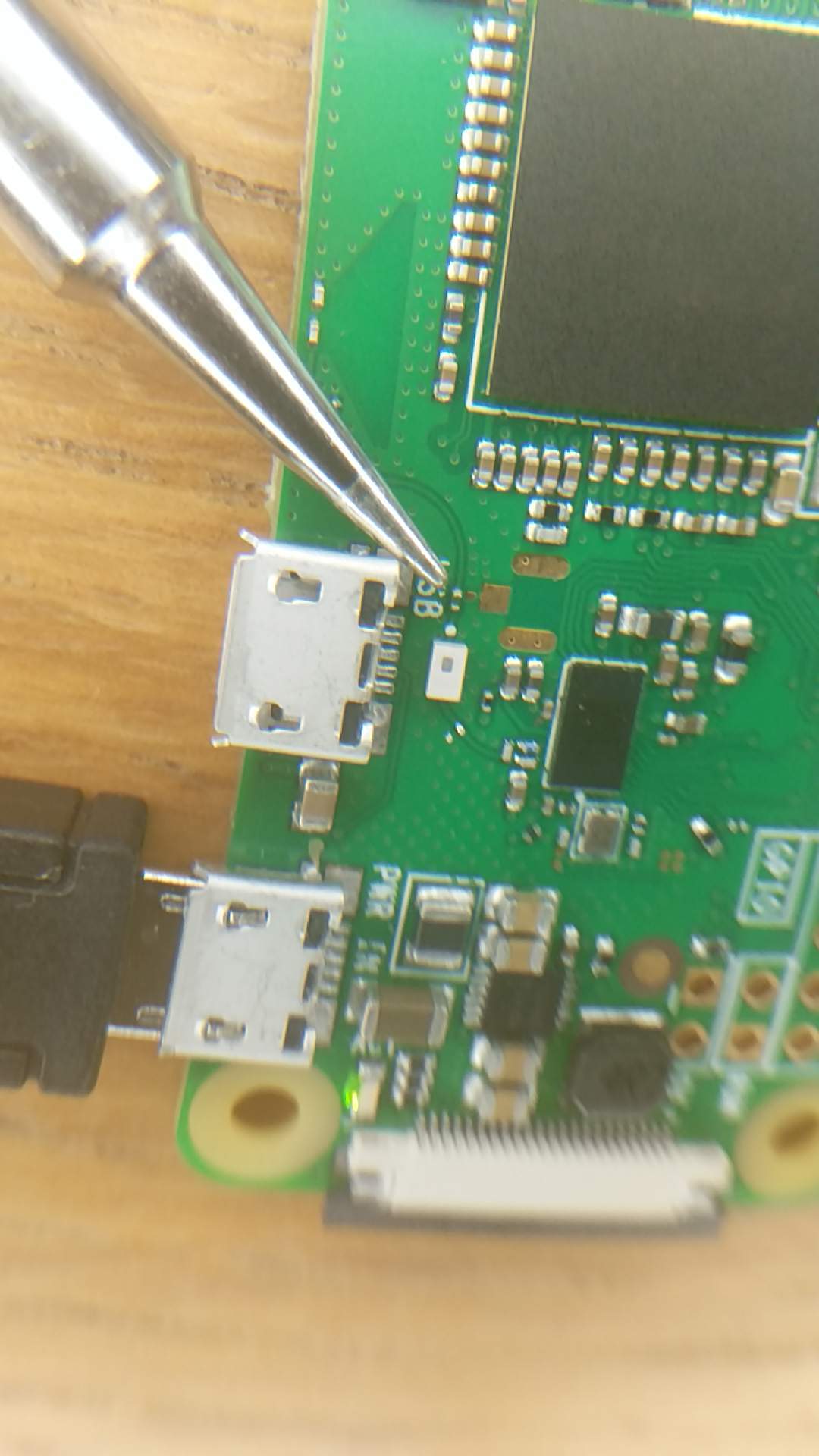
OMG, the 0 ohm resistor I have to move to enable the enternal antenna is the tiniest thing I have ever attempted to solder. You can just see it in the picture above the “S” in “USB”. I though the equivalent resistor on the Wemos was small, but the Pi’s resistor is far smaller…
Here it is next to the smallest soldering iron tip I have:
Also you clearly don’t waste any time, really good stuff so far. Nothing like diving in the deep end with a hardware modification ;) Would be interested to see how the external antenna fares against the onboard one, I’m guessing it will be quite considerably better.
One of the things we wondered about after you’d left is how it might hold up against humidity- a weather-sealed box being the obvious choice in retrospect. Do you have an idea what project box/enclosure you’re planning to use?
I’ll probably use the same type of box as I used for my weather station.
I’m really nervous about attempting to move that resistor! I have a pair of needle-nosed tweezers which might help, but they are not the heated type. And my smallest soldering tip looks massive compared to that resistor. Why oh why didn’t they use a larger resistor? Perhaps they never actually intended end-users to move it, but imagined they might sell a version of the zero with the antenna connector fitted and the resistor already in the appropriate position.
Don’t get too used to me moving this fast. I’m off work this week. During the normal working week, I get very little time to devote to hobby projects.
You should just be able to heat the whole resistor and then pluck it off, without needing to directly heat the ends. Probably wont do the resistor much good, but I imagine it’s not going back on anyway!
Just too far beyond my skills, tools, eyesight, steadyness of hand…
There are so many problems.
Got the 0R resistor off and almost immediately lost it. It was like a bit of dandruff.
There are other components so close to the antenna socket pads that several times I got blobs of solder stuck on them, causing solder bridges all over the place. Took ages to remove. I tried solder sucker, solder braid, but they were just too crude for the job. Got most of it off, I think. And that was using 0.5mm solder and an illuminated magnifying glass.
Got solder all over the socket itself, making it a very tight fit to get the antenna connector on, resulting in breaking the first socket off the board within minutes and then having to destroy it to get it out of the antenna connector.
Making the solder bridge was just a case of trying over and over, but the position of the 3 pads means that molten solder wants to take the shortest path, and that is to the wrong pad. You can’t just put a blob over all three pads because then both the pcb and the external antennas would be connected at once, making the impedance all wrong and the combined gain worse than either alone.
The Pi is still working. I will re-test shortly. Need to relax and let my eyes un-cross.
I cannot recommend attempting this without a stereo microscope, a hot-air solder station, solder paste, and the eyesight and steady hands of a surgeon!
Testing showed that the signal strength got worse, not better. I think it more than likely that this was due to my poor job of soldering, rather than the quality of the antenna, because an identical antenna significantly improved things when I tested it with the Wemos.
Packing up for the evening, I just tried to remove the antenna plug, and, again, the socket came unstuck from the Pi and is lodged in the plug. I broke it getting it out.
So unless I can find a Zero already set up for an external antenna, its not looking good for the Zero on this project.
Does anyone else feel up to some delicate soldering?
I dare say you’ve convinced me to have a punt at it, to see if I can get it done. My soldering skills tend to change with the wind though, some days stuff is beautiful… others… unforgivable!
We also have a hot air gun, which will surely help. Although there are a lot of tiny components near that socket landing that could be blown to the four corners of the warehouse at a moments notice.
I’ve no idea if we’ve got any of those SMD connectors though.
I’ve got 2 left. I can post them to you. They were dirt cheap from China. I can order more on AliExpress, I have no immediate need for those 2 I have left. Let me know
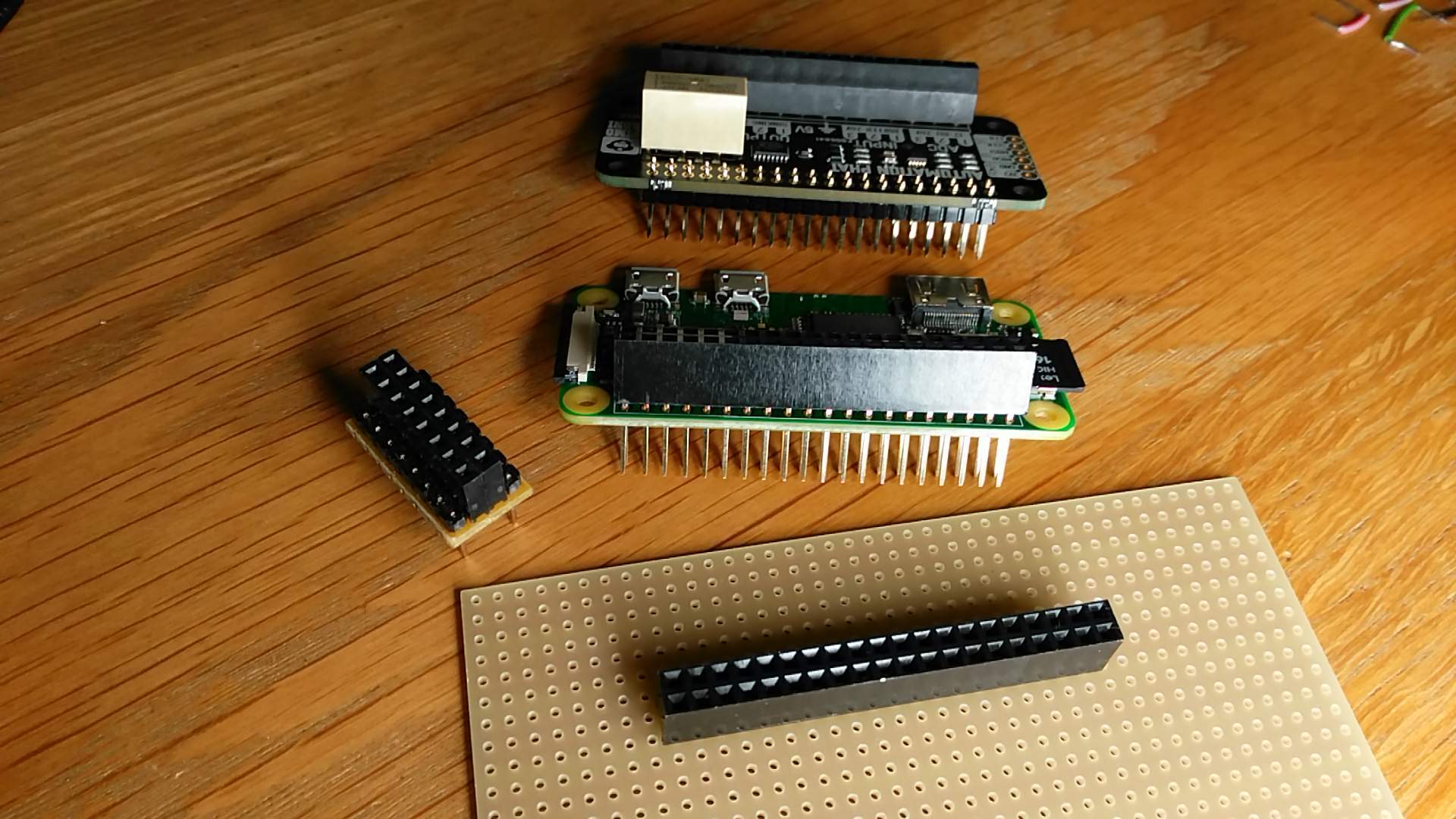
For prototyping purposes, as well as for use in the final build, I am planning to solder a stacking header to the Pi. I think this should be a fine idea from an electrical point of view, but I could do with some advice from more experienced Pi users as to whether this arrangement is going to cause me problems.
The picture below should give you the general idea:
The automation phat will have the female sockets soldered on the underside.
The Pi will have the stacking header soldered to it, again with the female sockets on the underside. The phat can then fit onto the top side of the Pi.
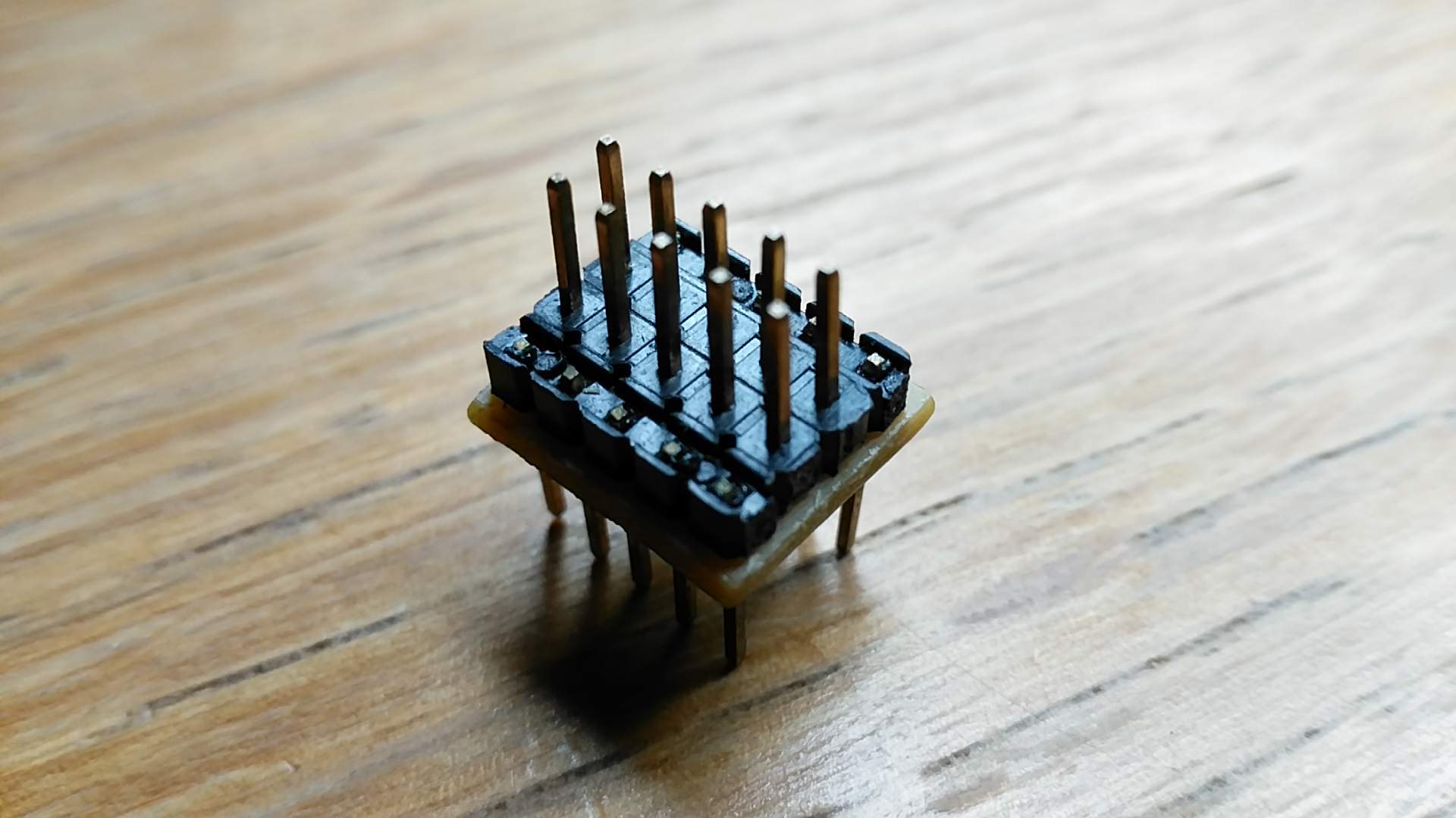
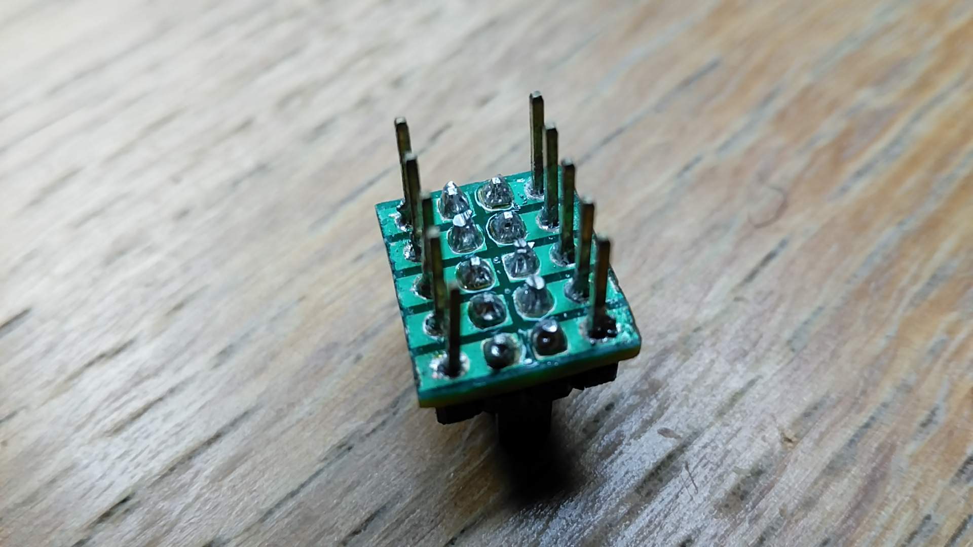
I will build a breadboard adaptor similar to the 8-way adaptor shown, but obviously it will be 40-way.
The breadboard adaptor will be made from a cut-down strip of tripad board. This is convenient because it has breaks in ths strips between some rows. Hopefully the images below show how this works.
either arrangement will work… I personally would go with the first, so you can just plug the Pi in something like this, as well as making it ‘HAT friendly’.
That said I’m unsure how practical your adapter will be for prototyping purposes, won’t the Pi be in the way on one side and making adjustments difficult (without powering off the Pi and removing it anyhow)?
@RogueM thanks for the reassurance. Yes, sometimes the pi/breadboard adaptor will be in the way of easy wiring changes. I did consider purchasing that Adafruit adaptor. But I decided that I would prefer to try to keep things neat and rigidly mounted on the breadboard, avoiding ribbon cables. I may need to run wires from the phat onto the breadboard, and I think it would all get messy and fragile. Also, the Adafruit breadboard adaptor would be wider than my home made one, taking up more of the width of the BB and possibly forcing me to place some wires under the adaptor.
I have always been told that before making any changes to a breadboard circuit, one should always disconnect the power, to avoid risk of damage to the components. So this will lead to frequent pi reboots, which will be a pain given how long that takes. I am used to Arduino, which takes 1~2 seconds to “boot”. Is it generally considered safe and normal to plug/unplug a pi from a circuit while still powered up?
indeed, you shouldn’t just ‘pull the plug’… 9 times out of 10, or 99 out of 100 if you’re lucky, it will be fine but at some point you’ll brown out your OS.
I assume you’ll be using ssh so that should be no problem to shut down the proper way? if not you may want to look at wiring a button to do that for you, using something like https://github.com/pimoroni/clean-shutdown
… that is why I would personally try to get the Pi out of the way and have full access to the prototype, if for no other reason but being able to squeeze a multimeter or analyser in place to debug. When you move to your final build then those considerations should be irrelevant.
The point I was making was that the first arrangement can be plugged in directly into a cobbler - which might be handy in the future - the setup would be functionally equivalent to your homemade version in any case, no more and no less wires involved, your Pi would simply be off to the side, with a clear view/access to your prototype.
Anyhow, not trying to convince you that investing in a cobbler would be worth it (I rarely use mine), just that from experience I would expect to want to debug something at some point and not having clear access would drive me mad very quickly.
Sorry, I was not being clear. I was not suggesting removing power from the pi without shutting down first.
The point I was making was that it is not safe to reconfigure a circuit while power is connected. You can all too easily cause a temporary short, or a current spike could damage a component. This includes, I would imagine, disconnecting or reconnecting the pi from the rest of the circuit (it is after all just another component).
So the safe approach would be: 1. Shutdown pi; 2. Disconnect power; 3. Disconnect pi if it is physically in the way; 4. Make changes to circuit
Yes that process would be fine. In the past I changed circuits on fly but after a nasty short that blew a pi I always disconnect the pi from my circuit before tampering