Hi everyone, let’s see if you can help me solve this mystery.
As I mention in the thread title, the combination of an Inky Impression 13.3" + Witty Pi 4 L3V7 + Raspberry Pi Zero W2 does not work. It doesn’t matter whether I run an example or my own code—the result is always the same: the screen doesn’t even try to refresh, and no errors are thrown. If I remove the Witty Pi 4 L3V7 everything works perfectly.
At first I thought it was a GPIO conflict, but I kept running tests just to rule things out. I also tried with another Raspberry Pi Zero 2 and with a Witty Pi 5, and I always got the same results.
But the exact same setup works perfectly when using a Raspberry Pi 4!
So I’m assuming there’s something about the combination of Raspberry Pi Zero W2 + Witty Pi 4 L3V7 that the Inky doesn’t like. Any ideas?
Yes, it’s just a screen refresh issue. With the Raspberry Pi 4 it works as expected, but with the Raspberry Pi Zero 2 my script completes without errors, yet the display does nothing.
Ok, to narrow it down: are you using the same OS-versions for the Pi4 and for the Pi02W? If not, first rule out that this is the cause of the problem.
My next step would be to instrument the driver. I assume you are using the code from Pimoroni, and since this is Python, it is easy to add some prints at various points. Here I would also print the timings whenever the driver talks to the SPI bus. Note: the driver is fairly simple and easy to read. You won’t understand every line but you should see what is going on.
Another option is to trace the SPI-bus. This sounds more complicated than it is, you only need a Pico and a bunch of cables for it. But I think this is something for later.
Maybe it is also a mechanical problem?! Are the pins of the Pi4 a bit longer than the pins of the Pi02W? I assume you have a stack: Pi - WittyPi - 13.3"-eink?!
I am trying to do the same thing with my 7.3”. It looks like Witty Pi uses GPIO 17 for power monitoring of the pi to determine it’s on/off state, and the Inky uses that same header for determining the screens busy state. Sucks because I really want to use the zero 2w for my project. Looks like I’ll be getting RPi 4 instead unless someone can figure out a simple fix
I forgot an important test I did. I ran the same test with the Witty Pi 5, which in theory only uses the SPI, I2C, 5V, and ground GPIO pins, with the same results: it doesn’t work on the Raspberry Pi Zero 2, but it does work on the Raspberry Pi 4.
This is an important information. I am still interested if it could be a mechanical problem. Did you measure the length of the pins already? AFAIK, Pimoroni supplies an extension header. Have you tested the Pi02W together with this extension header?
I use the same GPIO extender for all the tests—one that has longer pins so it sticks out from the WittyPI and allows me to connect the Inky. I usually use a GPIO cable to connect the pins that stick out of the Witty to the Inky. I do this because the Inky is very, very delicate and I prefer not to be messing with the connection constantly. In any case, with a direct connection, without the cable, I get the same results. The operating system is always the same.
I’ve modified the Inky driver to add logs everywhere to see if I can find any new useful information. When I run the test, I’ll let you know.
I wonder if the upgraded GPIO drivers of the rpi 4 are better at filtering the noise coming from both the Inky and Witty Pi on GPIO 17 then, where the zero 2w is seeing the BUSY signals from the Inky as power monitoring calls for the Witty Pi. My attempted fix was going to be running a jumper from BUSY on the Inky to a free pin on the pi and then pointing to that one in Inkys software.
I don’t think the busy pin is the problem. The inky driver checks if the pin is driven high by something else and then uses a default timeout instead. This should slow things down, but it should not prevent screen refreshes. And the Witty Pi only sets this pin high once at startup, so this might not even be relevant.
But testing it like you are planning to do is certainly better than speculating.
Otherwise, the difference in GPIO drivers might indeed be a problem. The Pi02W is basically a Pi3 chip, the Pi4 is newer. This could result in different rise times of the pin-levels due to different drive strengths. Adding the Witty Pi could change this in subtle ways, even if the WittyPi does not use the pins. This would explain why the Pi02W works without the Witty Pi.
What you also could do is to lower the SPI speed (the driver uses 10MHz). But if edges are the problem, this will not help.
I completely agree. As I already mentioned, exactly the same thing happens with the Witty Pi 5 Hat+, and with this Witty model there should be no GPIO conflicts of any kind. I think you’re on the right track with what you’re thinking.
In that case I’m going to avoid soldering any jumpers for the time being and keep an eye on this thread if anyone has any breakthroughs. If not I’ll be getting a pi 4 for this project. You said the pi 4 didn’t experience any issues with with Witty Pi 4 L3V7 power cycling with the button or a schedule?
I finally managed to solve the problem with the Witty Pi 4 L3v7 + Raspberry Zero 2 + Inky Impression 13.3"! You need to lower the SPI speed. In my case, I edited /boot/firmware/config.txt and added: dtoverlay=spi0-0cs,clockfreq=2000000
It seems that the Zero 2 has an SPI bus that is less tolerant to impedance, and the signal degrades when passing through the Witty. If you lower the SPI frequency, it gets fixed.
Nice! Glad you were having this issue same time I was or I don’t think I would have figured that out. Going to try this later and report back if it fixes mine as well.
Legend. This does also seem to fix the issue I had with my PiSugar 3. I still have to do some more testing to be sure, but a quick test does seem to work.
@hel: could you please add this to the docs? I think many user will combine this display with a power-managment hat like the Witty Pi or Sugar. Updating the driver might also be an option but this would also slow down users of a more recent Pi.
I did some further testing but unfortunately this isn’t a solid solution for me. It seems that it only works when the battery on my PiSugar is disconnected and connected again.
I was finally able to test this fix out and it is working for me as well on Impression 7.3”. The screen can refresh no problem now.
I’m noticing an issue with Witty Pi than I’m unsure is related or not, but when using the power button on Witty Pi it powers down the pi but does not cut power. The red power led stays on and I can here power being delivered. Shutting down the pi through ssh or remoting in works and cuts power properly though so it’s not a huge deal. Also, powering on with the button works as expected
What you’re saying is indeed caused by the conflict with GPIO17, but there is a solution. I’ve modified the Inky library to make it work. In the file inky_el133uf1.py you have to change the BUSY_PIN variable. In my case I set BUSY_PIN = 19 because that pin isn’t used by the Witty Pi.
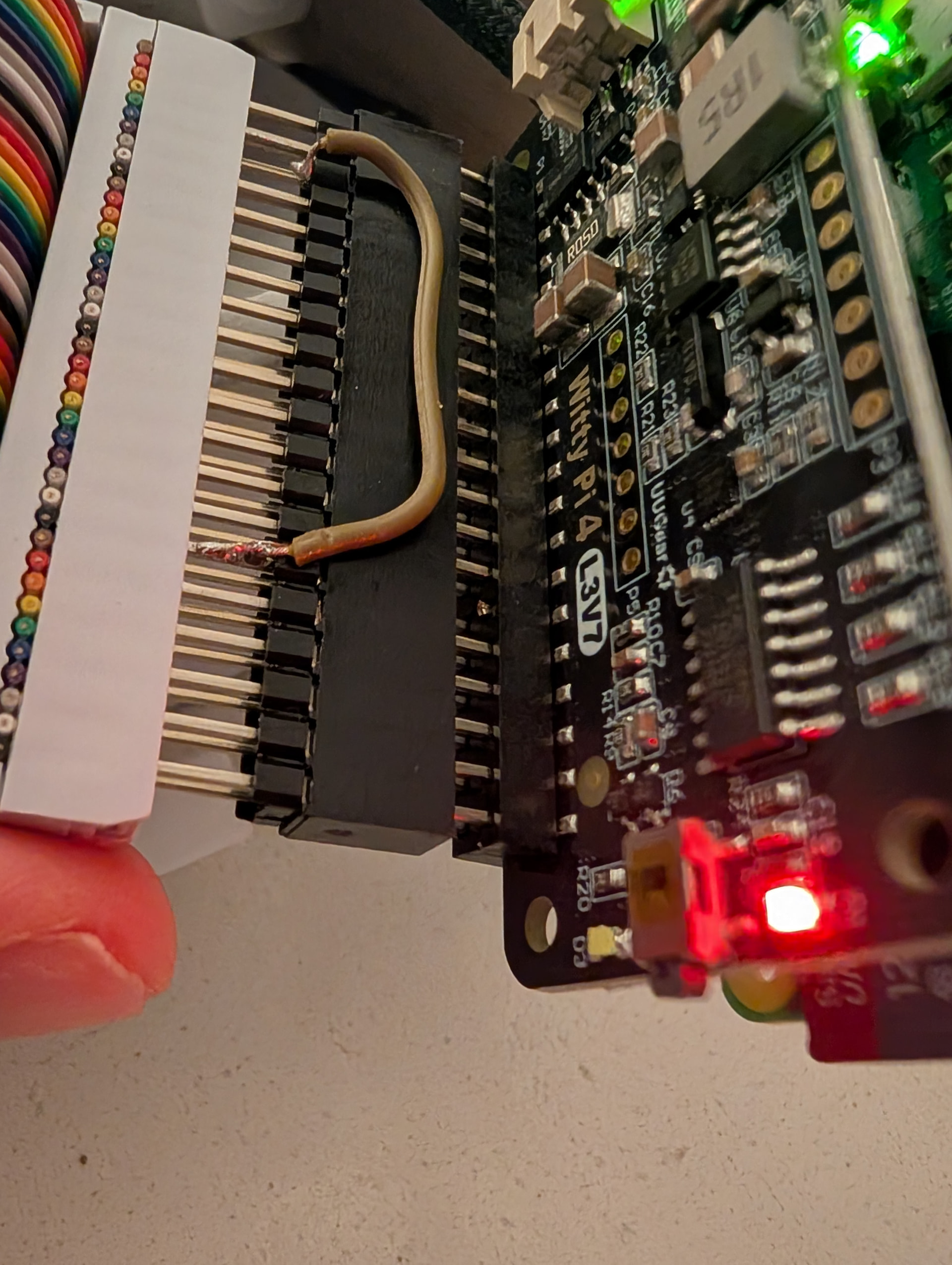
Once that’s done comes the tricky part: you have to reroute the GPIO19 that comes out of the Witty Pi so it reaches GPIO17 on the Inky (this is important). I did it this way:
Used a tall stacking header from the Raspberry Pi to the Witty Pi so the pins stick out on top of the Witty Pi.
Cut the GPIO17 pin flush with the Witty Pi board so it doesn’t make contact.
Added another stacking header on top. On this one I cut the GPIO19 pin and soldered a small wire from that GPIO19 position to the GPIO17 position.
I’ll try to attach a photo, it’ll probably be clearer.
I’m sure there are cleaner ways to do it.
By the way, the solution I originally suggested is inconsistent — sometimes it works, sometimes it doesn’t. I no longer know if it’s just random or related to the root cause.