Looking at the schematics. It seems like there are the following connections between the CPU and GPU. How are any of these connections exist between the CPU (A) and the GPU (B)
- I2C (SCA, SCL) also to the Stemma/QiiC connector
A. Is the GPU connected to the I2C to act as a port expander as explained in GPU Port Expansion - I2S (PCM Data, BCLCK, LRCLK)
A. Didn’t find any docs - VSync
A. It isn’t clear from this comment which RP2040 is loading what during the vsync interval During VSync, data is loaded into the active sprite buffer in GPU RAM (that’s the internal memory of the RP2040 serving as the GPU) Scanlines docs - UART (TX/RX)
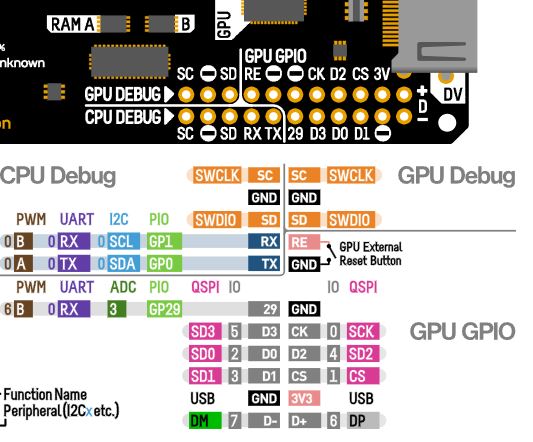
A. Didn’t find any docs - debug port (SWDIO/SWCLK)
Found this google sheet mentioned on GITHUB. It says private here but I had no trouble accessing.
Created this diagram looking at the schematics