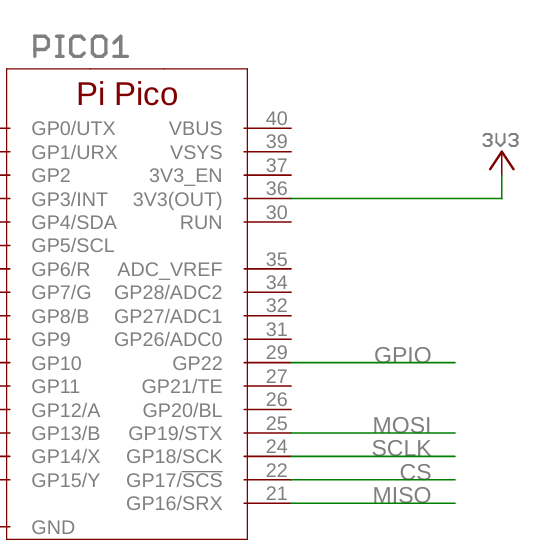
I’m struggling to get any image out of my 1.3" SPI Colour Square LCD (240x240) Breakout. I’ve wired it to my Pico 2 W per the pins on the item page. 1.3" SPI Colour Square LCD (240x240) Breakout
I’ve installed the latest micropython Pico 2 W .utf from here:
And have tried out the example here (I can’t put more than 2 links in a post as a new user!):
I don’t get any errors at all, the screen flashes (BL turns off and on) when I execute my code but no graphics show. Does anyone have any suggestions on how to debug this further?
Ah ok, thanks! Do you have any recommendations for testing which contacts might have a poor connection? I want to use the display in a project that will eventually be soldered but I’m not quite ready yet.
You were absolutely right by the way! Applying a small amount of pressure to the top of the display has made sure all of the contacts connect and I am seeing results! Thank you so much!
That’s a scenario that plays out here quite often. I can “almost” solder with my eyes closed, lol. But I’ve had years and years of practice, showing my age much, =).
Anyway, I use a lot of those Pimoroni breakouts in my projects so I bought a Breakout Garden Pack and Hat etc. Easy Peasy to test it on a Pico or Pi with no soldering. Saves on the “why wonder why” moments.;)