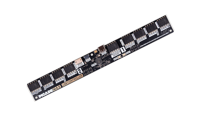
EDIT:
Found a schematic, will have a look…
EDIT2:
So, there’s a matrix, from what I understand one side of the button is hooked to a drive signal, the other to a diode and then into a read signal. Closing the button connects drive signal to the read signal. Setup so that certain functions share drive and certain function share read (two functions per read, 6-8 share a drive).
I’m guessing, due to diodes, drive sends high signal in a pattern, high signal goes through diode and into input.
Using the joystick drive (which drives the directions of the two controllers) will not work for button A as I had hoped.
So unless JOY_DRV is active at the same time as SW_DRV_1 I won’t be able to use just a single wire to control UDLRF - as the JOY_DRV and SW_DRV_1 probably aren’t active at the same time as SW_READ_1 goes to P1_JOY1 and P1_B1…
… how do I handle this? Need in between electronics?
I’ve got quite a few computer games on the arcade machine so I was planning on adding a 9 pin DSUB-connector for C64/Amiga/Atari… etc so I can use the proper controller.
(I had actually everything prepared)
It’s perhaps known that these basic versions of the controllers only connect UDLRF to GND.
The four way directions is no problem, it’s just four directions connected to the same wire, same as function.
All the buttons are hooked up with two wires each, neither of them is GND, I measured about 60 Ohms to GND on one of them. Is there another way to solve a fire function than for example adding a relay to connect the normal two wires - which is an option I have considered.
Is there a spot I can ground (use the “0” signal) to activate A-button functionality?
I can of course use any of the UDLR for player two as fire and remap all emulators - then remap again for anyone who wants to use the on panel controllers unless they want to use second controller for fire button function.
(Getting any configuration at all to stick with Recalbox is an entire different problem.)
Ideas?
Has anyone checked the board, I imagine there’s no schematic?
